Making the Jump to Electric
White Paper
A step-by-step guide for replacing hydraulic axes with modern electric actuation — a transition that’s as easy as 1-2-3.
By Ryan Klemetson, Business Development Manager, Tolomatic
Hydraulic actuators have been a mainstream factory automation technology for decades — and they’re not going away anytime soon. At the same time, however, advancements in electric cylinders are prompting more machine designers to ask the question: which technology is better for the job? The answer, increasingly, is electric actuation.
In industries ranging from timber to packaging to medical devices, there are many compelling reasons to make the switch from hydraulic to electric actuators. While hydraulic cylinders are rugged and capable of producing extremely high forces, their electric counterparts offer more flexible motion control capabilities, don’t require as many components and present minimal environmental and safety risks. Thanks to their better process control, electric actuators go a long way toward enhancing product quality, reducing scrap, increasing throughput and improving overall profitability.
Whatever the reason, perhaps you’re looking to switch from hydraulic to electric actuators — a technology leap that may feel like falling into an unfamiliar world. The good news is the transition boils down to three, easy-to-follow steps.
Step 1: Determine the Actual Forces When Sizing Your Cylinder
The first step to moving from hydraulic to electric actuation technology is to know your system’s required forces, a process that will take you beyond simply multiplying pressure and area. This equation, Force = Area x Pressure, assumes the maximum-rated pressure of the hydraulic system and will yield a value that translates to a larger-than-necessary and therefore more costly electric cylinder.
To avoid oversizing your electric cylinder, we recommend measuring the hydraulic pressure as your process is operating, rather than relying on the system’s maximum-rated pressure. While the measurement location will depend on the accessibility of the installation, the closer it is to the point of work — i.e., the hydraulic cylinder — the more accurate the pressure reading will be (Figure 1). While it may be difficult to get an exact pressure reading, even an estimation within 15 percent of the actual force will provide a reasonable range.
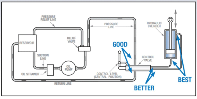
Figure 1: Where to measure pressure when determining actual application requirements.
Typically, you have three measurement options:
• The first option is to measure pressure at the valve. Although a common method in hydraulic-to-electric conversions, this location is furthest from the point of work and may cause errors in actual versus measured pressure values.
• A better option is to measure pressure between the valve and cylinder. Keep in mind that needle valves and other inline accessories may influence the pressure value.
• The best option is to measure pressure at the cylinder itself. While this method yields the most accurate pressure reading, it may be a challenge to access this location.
Measuring pressure at the hydraulic cylinder — specifically, on both sides of the cylinder — will yield the most accurate force values. Because cylinders have unequal surface areas relative to the piston and rod sides, we recommend placing gauges on both the extend and retract ports. From that point, you can calculate the effective surface area (Figure 2) and analyze how the pressure interacts with that area to generate the force and its corresponding reactive force.
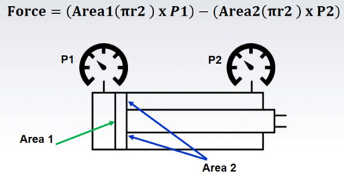
Figure 2: Accounting for the effective surface area is the preferred method for calculating actual force requirements in hydraulic-to-electric cylinder conversions.
We also recommend that you measure the system’s return pressure in addition to the working pressure. Each hydraulic system is different, and while return lines usually have minimal back pressure, some circuits will have high return pressure between the cylinder and the valve. In these instances, the pressure will have an impact on the cylinder’s output force.
To demonstrate this point, consider the following two force calculations:
Method 1: System Rating
Where:
• Cylinder bore: 1.5 inches
• Cylinder rod: 0.75 inches
• Maximum system pressure: 1,500 PSI
Force = Area × Pressure
Force = (0.752π) × 1,500
Force = 2,650 lbf
Method 2: Effective Surface Pressure
Where:
• Cylinder bore: 1.5 inches
• Cylinder rod: 0.75 inches
• Required pressure (P1): 1,200 PSI
• Back pressure (P2): 250 PSI
Force = (Area1 × P1) – (Area2 × P2)
Force = (0.752π × 1,200) – ((0.752 – 0.3752)π × 250)
Force = (1.767 × 1,200) – (1.327 × 250)
Force = 1,788 lbf
The value 1,788 lbf represents a 40-percent reduction in calculated force compared to 2,650 lbf, highlighting the importance of using accurate application data to avoid oversizing your electric actuator.
Step 2: Define Your Motion Profile
The next step in transitioning from hydraulic to electric technology involves understanding your motion profiles, cycle rates and throughput. One important question to ask yourself is: which is more critical in your application: cycle rate or linear velocity? In other words, is it more important to move at a given rate (cycle time) or to move a distance in a given time (velocity)? The answer to this question will impact your motion profile (Figure 3) and, by extension, how you size your actuators and drives.
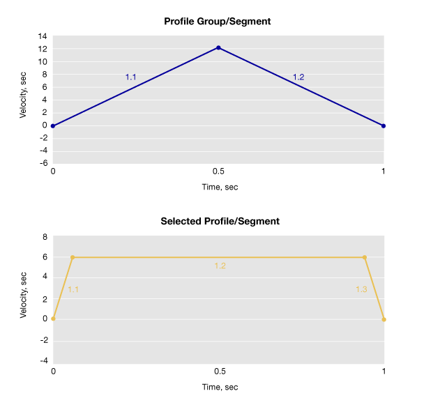
Figure 3: Your answer of whether cycle rate or velocity is more critical to your application will affect your motion profile — and therefore your component selection. For example, these motion profiles both depict a movement of 6 inches per second in two unique ways.
For example, high cycle rates require faster movements, meaning your actuator must be able to accelerate and decelerate more quickly. The motion profile will therefore incorporate details like how quickly the actuator must accelerate to its top speed and then decelerate to a stop. Keep in mind, higher cycle rates increase heat generation and mechanical wear on your components. To help you optimize your motion profile and keep your wear minimal, companies like Tolomatic offer sizing tools to help you select the best components for your application.
The tool will even automatically flag components that exceed their thermal limits.
Step 3: Use a Reputable Sizing Software
Good actuator sizing software is an indispensable tool as you move from hydraulic to electric actuators. For example, Tolomatic’s software can help you size and select electric actuators based on your application needs. This tool automatically calculates and determines which actuators will work best given your speed, force and life requirements.
The process begins with defining your critical parameters, including motor mounting, actuator orientation, stroke length and environmental conditions. Next, define the loads and velocities for the stroke segments you specify; the number of segments and their characteristics are up to you. Finally, the tool displays Tolomatic products that fit your parameters and motion profile.
Electric Actuators in Action
The timber industry is one area where electric actuators are increasingly replacing hydraulics. For example, in one recent application, a lumber company wanted an environmentally friendly solution to move saw blades as they cut logs. This solution needed to avoid contaminating the wood while being rugged enough to withstand the lumber mill’s wet and dusty environment. It would also need to resist shock since the logs regularly bumped into nearby equipment. The company was having issues with its previous hydraulic system; due to temperature fluctuations within the mill, the cylinders were experiencing cold starts, premature seal wear and reduced performance.
The RSA series of electric rod actuators with roller screws overcame these issues, offering IP67 sealing and grease that could withstand a wide temperature range. These actuators were an environmentally friendly alternative to the previous hydraulic cylinders, and they successfully increased the reliability of equipment, reduced maintenance and minimized downtime.
Get Started With Electric Today
From greater energy efficiency to more flexible motion profiles, there are many reasons to make the switch to electric actuation technology. Electric cylinders are increasingly capable of delivering high forces comparable to that of hydraulics, making them a viable replacement in a growing number of industrial applications. While switching technologies may seem daunting, you can begin the process in a few easy steps. And remember, finding a knowledgeable electric actuator partner will go a long way toward streamlining the transition process.
To get started, visit: www.tolomatic.com.
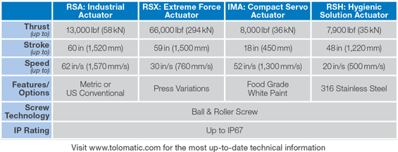
Table 1: Product comparison of select Tolomatic electric actuators.
Remember: Your Motion Control System is Still a System
Moving away from hydraulics means you’ll no longer need a hydraulic power unit, reservoir and filter. Instead, you’ll need to specify mechanical components, as well as a motor and drive. To this end, it’s important to remember that your motion control system is still a system. Your answers to the questions — what do I need for my application? — will determine your choice of components, which should include the following:
Electrical components. Ask yourself what your power needs are. Do you require 230, 460 or 600 volts? Do you need single- or three-phase power?
Feedback devices. Do you require a resolver or encoder? What type of encoder do you need — incremental or absolute?
Cabling. Though frequently an afterthought, cables are the all-to-often culprit behind actuator failure. Make sure you follow your drive manufacturer’s recommendations on cables and dressing requirements. In addition to saving you lots of headaches, the right cabling will go a long way toward minimizing electrical noise, which is one of the most common issues facing new electric systems.
Hydraulic or Electric?
Other Factors to Consider.
When transitioning from hydraulic to electric actuators, here are some high-level considerations to think about:
-
- Cylinder envelope and mounting. Electric actuators aren’t a simple drop-in replacement for hydraulics. They often require additional space, as well as mounting design work.
- High forces in tight spaces. Although electric actuators can achieve high forces, they’re not as power dense as their hydraulic counterparts, often requiring additional space and precluding their use in very tight spaces.
- Stroke length, velocity and force. Longer stroke lengths beyond 60 inches may reduce an electric actuator’s maximum velocity and force due to screw buckling and critical speed limits.
- Mobile applications. While 12/24 VDC electric actuator options exist, they’re limited in both force (<4,000 lbf) and duty cycle (roughly 10 percent). Applications involving high shock loads like construction, mining and agriculture may pose issues.
- Two-position applications. While electric actuators require a higher initial investment than hydraulics in two-position applications, you can achieve ROI once you consider your total cost of ownership — e.g., zero leaks, lower utility costs, reduced maintenance and zero environmental risk.

 Kontakt zu einem Ingenieur